Saturday, December 12, 2009

Electronics workshop organization 1

My next project will be to organize my electronics experimental workshop. Currently I have a good set of tools, test instruments and a large table equipped with good lighting. However my components are stored in the traditional and so called junquebox! It is extremely difficult and tiresome to hunt through the components in order to find a resistor or capacitor or transistor. In fact on many ocassions I confess to giving up and simply taking the easy but expensive way out. ie drive to Radioshack or order a new component online. As a result I have a fairly large pile of components accumulated over many years.

Searching on the internet does not show up many results on how to go about this organization of a workshop and associated components. I thought that someone may find it useful to follow my project as I proceed and as I 'learn by doing'.

I first laid out all my small components on my workbench. This allowed me to see what I have and to determine what size component storage I will need. I have also now embarked upon a mission to collect as many empty containers from the household trash as possible. Having paid a visit to the local container store I realize that most of those containers are far too expensive. Purchasing these containers would cost as much as the components for a complex radio would cost! I did go to Dicks Sports Store and purchased a number of fishing lure boxes for about $5.66 each. These provide about 34 storage bins for small components such as resistors and capacitors.

I started my organization with the capacitors. I soon figured out that the most efficient scheme would be to store components in designated BINS. Then link the BIN number to details about the components in a catalog on an excel spreadsheet. Having ironed out a few bugs I believe I now have a good and practical set up. Essential to the operation of the catalog is the ability to search. This means that even though the BIN numbers may be illogically numbered from a components perspective, at least it is possible to cross reference and search for the desired component. I have, to date, recorded approx 550 capacitors in the system and already this has given me insights into the power of a searchable catalog. The result of this project will be that all components will be searchable through the excel spreadsheet mechanism. This will enable me to quickly and painlessly try different components in the circuit in order to optimize my design.

To catalog a component my method works as follows. Using capacitors as an example:


Identify the capacitor spreadsheet in the excel components book.

Identify the capacitor value that requires storage.

Type in the capacitor value into the 'Find' function on the catalog spreadsheet. eg. 100pf. Typed in as '100'. If the value is greater than 999pf then type the value as mfd or microfarads. For example .001 as opposed to 1000pf. (Note that I need to note this rule on my catalog notes section.) Only type the number. Not pf or mfd.

If the computer shows a result I then increment the 'quantity' column, add any other known information such as tolerance or max working voltage.

I then identify the BOX number and the BIN number within that box from the spreadsheet.

Locate the BOX and the BIN and store the component if there is enough room in the BIN.

If there is not enough room or the component is a new component. Open a new line item in the spreadsheet and allocate a new BOX/BIN number. Enter the details of the component.

Store the component in the BIN.


To look for a component simply use the FIND feature on the spreadsheet to locate the component. Then if the component is removed then decrement the quantity in that BIN. If the BIN becomes empty then enter a replacement component requirement in the 'COMPONENTS TO BE ORDERED' Spreadsheet. The same procedure would apply to the case where a component cannot be located. In this case the Component should be added to the COMPONENTS TO BE ORDERED SPREADSHEET.

This method is very efficient from a space point of view since it allocates BINS only for components that exist. Since space is at a premium in my workshop I cannot afford to have empty BINS just in order to adhere to a logical list. The problem is that components of the same category. ie Capacitors may exist in many different boxes. However the computer search feature will find the BOX and the BIN. It means that the computer becomes essential to the operation of the system. The BOXES and BINS are only marked with a Number for the Box and a letter for a BIN within a box. This means that by looking at the BOX you cannot necessarily see inside what is in it. Another benefit of this system is that it is very easy to redesignate a BIN for another type or component. It is just a matter of changing the entry in the computer.


No doubt there are catalog systems available out there. I thought that by developing my own I would have a very clear idea of what type of catalog system I need. Once I know this I can transfer my data over to another more robust and user friendly system. Should not be a problem.

Once I have all my existing components cataloged and therefore some control over my workshop environment I will then look at storing the catalog on my website in order to be able to access from any computer. This will be particularly useful when I am on the road and I am working on a design for a project. Having a master database online will mean that I do not have to contend with the headache of keeping multiple versions up to date.


Sunday, November 29, 2009

One Tube 6L6 Transmitter experiments 6


Having completed my 6L6 project for the time being with no doubt in my mind that I can improve the design still further with improved understanding. I read the RSGB Handbook 5th edition section on Transmitters and in particular tube oscillators. Revealed the link between the output impedence and how it impacts the behaviour of the oscillator. It states that you need to increase the capacitive load in order to stabilize the Transmitter. This is because the TX is only in the positive feedback stable condition when the feedback from the load is slightly capacitive. I found just the opposite on my TX ie as I increased the capacitive load the oscillator became less stable. I think this is due to a slight mismatch to the antenna load, meaning that in fact the load was still slightly inductive. Note that I did not try this test using a dummy load but instead I used my attic dipole which is not a perfect resistive load. However more analysis is required before I can be sure.

I was able to make a number of very good QSOs with stations all over the US this wekend and I received reports ranging from 459 to 589. Examples of contacts being WB3T, WB2PPQ, WA$DAX, KF8R, K9LWA. I find that even running full power at 4.5 wats still yields a stable transmitt signal although it is important to monitor the signal to be sure that it is indeed stable.

Tuesday, November 24, 2009

One Tube 6L6 Transmitter experiment 5

This evening I wound a 'final' coil which consists of 21 turns for the loading coil and approx 9 turns for the link coil. I noticed that the link coil turns were not that sensitive to the performance of the Tx.


Measurements as follows:


Power output into my attic antenna = 4.2 watts

Cathode current keydown = 30mA

Cathode current keydown with crystal removed (ie not oscillating) = 36mA

Plate voltage key up = 339 volts

Plate voltage key down = 326 volts

Screen voltage key up = 163 volts

Screen voltage key down = 148 volts

Frequency of operation = 7041.98 Khz

Cathode voltage key up with crystal removed (ie not oscillating) = 34volts

Cathode voltage key down with crystal removed = 8 volts

Cathode voltage key up with crystal operating ( ie oscillating) = 34volts

Cathode voltage key down with crystal operating (ie oscillating) = 8 volts (frequency changed when probe placed (indicating impedance loading)

Control grid voltage key up = 0 volts

Control grid voltage key down = - 18.8 volts (I assume this is an inaccurate RMS value?)


NOTE: Most interesting was that the frequency of operation was shifted to what appears to be the natural operating frequency of the crystal. ie 7040Khz when I connect the voltmeter across the control gris. Could it be that the additional load impedance of the meter was driving the control grid properly negative biased. In other words perhaps the negative bias of the control gris is not sufficient.


Next try adjusting the negative bias. I tried a number of combinations but in the end I was not able to really improve the performance.

I completed the coil construction and reassembled the Tx back to its original form. Now working very nicely at the above parameters. Next I will take some pics of my current vintage station including my HQ180 Hammarlund RX.

Monday, November 23, 2009

One tube 6L6 Transmitter experiments 4


This evening I experimented with various coil settings. Eventually settling on a configuration providing 4.5watts and 29mA Anode current. Reasonable signal with small signs of freq drift at the beginning of the transmission. Heard by NN5O but not able to complete the QSO. Freq of operation was 7042.11Khz.


A better quality signal is given at 3.5watts. About 31mA. Frequency of operation 7041.39Khz.


Next I will rewind the coil to the same specifications and clean up the installation. Reinstall the coil and test again.

Sunday, November 22, 2009

One Tube 6L6 Transmitter experiments 3

Now decided to try playing with the plate current. Tried putting a 220ohm resistor in parallel with the existing 220ohm cathode resistor to see what happens. Result. No appreciable change. Plate current measured as 29.8mA. Removed the resistor.

Now back to the original circuit and now trying a new tank coil with looser coupling. ie winding the link over the cold end. Seems to be better than the previous coupling.
9 turns. Coupling still loose. Sharp resonance and sharp dip. Power 2 watts. Stable freq.

Now tried tighter coupling. Got it very stable and looking good! Output power = 4watts with Anode curent at max dip showing a nice dip to 30.2mA. Keydown voltage =325volts. Therefore input power to plate = 325*30.2mA = 9.8 watts. Output power = 4 watts. Efficiency now 40%. Can I do better? Output freq = 7042.18Khz.

Further adjustments now very interesting since I am getting very close to the point where max dip on the input current is corresponding to max power output indicating a point of maximum efficiency and therefore stability.
29.7mA plate. Keydown plate voltage = 326volts. Input power = 9.68 watts. Output power now 4.75 watts. Efficiency = 49%. Excellent.

Now try raising the screen voltage and see if can get more power? Raised it back to original spec. ie 191 volts on key down. Now raised the plate current to 35mA with no difference in power output and freq not as stable. ie less effieicnt now.

Now feel like I have arrived at a good result for the tank coil. Next step is to wind a solid coil using the same dimensions.

Saturday, November 21, 2009

One Tube 6L6 transmitter experiments 2

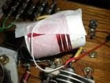
Configuration: My 6L6 with the tank circuit disconnected and instead using the tank circuit from an old Knight T-50 Transmitter (refer to attached pic).

Max Output power = 6.7 watts

Frequency varying. On key down the freq would start out at 7043.4 Khz and then drop to 7042.5Khz over a period of 7 seconds. Thereafter the freq would abruptly change back to 7043.4Khz. As the key is kept down the freq would gradually stabilize at 7043.8Khz after a period of 30 seconds. During this 30 seconds the frequency would oscillate slowly around these two max and min points and then settle down and stabilize. If the key is then lifted and then immediately key-on the settle down point is still quicker but still takes time to settle down. Note that the freq varies both up and down. ie not just up or down but both.

Tried moving the RFC in the plate circuit away from the voltage divider for the screen voltage. This had no effect.

Added a different capacitor across the screen voltage divider no difference.

Crystal noted also to get warm. Only gets warm on key down.

However changing the crystal to another one oscillating at 7050Khz does not seem to improve matters.

I blew cold air onto the crystal and it immediately started to oscillate similar to key down and then settled down much the same as the initial key down period. Indicating that temperature change in the crystal is causing the frequency change. I can definitely feel the crystal getting warm. Is there somethng wrong with the biasing of the contol grid? Why is the crystal getting hot?

Is it that the screen voltage is too high? In this circuit the screen acts as the plate for the oscillator. Note that the oscillator is stable when the Anode plate is not loaded up.
Measured Plate voltage Key up = 337volts
Measured Screen voltage Key up = 219 volts
Measured Plate voltage Key down = 319 volts stableMeasured Screen voltage Key down = 197 volts stable and not changing with freq change of the oscillator.

I detuned the tank circuit and thus took the load off the plate. The key down screen voltage is now measured as 202volts. ie a 5 volt difference to the loaded voltage. Frequency is now more stable for sure. Crystal does not appear to heat up.

Question? Why is the crystal also operating so far off frequency? Would expect it to oscillate on 7040Khz yet it is in fact oscillating 3 Khz above the resonant frequency. This must indicate some heavy reactance in parallel with the crystal.

Tried disconnecting the Anode plate voltage and left the screen voltage in place. Result. The oscillator was perfectly stable with excellent shape.

Measured voltages with Anode disconnected.


Screen Voltage Key up = 219volts
Screen Voltage Key down = 173volts
Note that the 173 volts is a full 219 - 173 = 46volts drop.

Compared to the situation with the Plate connected. 219 - 197 = 22 volts drop.

Oscillating frequency now dropped to 7042.69 Khz.

Cathode current with only screen grid connected = 11.77mA

Next I will try a voltage divider of 12.5k / 12.5 k which will drop the screen voltage significantly.

Measured screen voltage key up = 162 volts
Measured screen voltage key down = 119 volts
ie voltage drop = 162 - 119 = 43 volts
Cathode current with only screen grid connected = 7.68mA
Now reconnect the Anode Plate voltage and do the tests again with lower screen voltage.

Frequency now stable, however the power output has dropped as would be expected.

Max power output now 4 watts (as opposed to with higher screen voltage). However significant chirp at this point. Although the freq is basically stable. Indicating room for improvement on chirp. Power needs to be backed off to abou 3 watts to reduce chirp.

Power = 4 watts
Key up anode voltage = 339volts
Key down anode voltage = 325volts

Key up screen voltage = 162volts
Key down screen voltage = 146 volts

Cathode current keydown = 32.8mA
Screen current keydown (Anode disconnected) = 8mA

Power input = 325*32.8mA = 10.66 watts

Efficiency = (4/10.66)*100 = 37.5%. I reckon I should be able to do better.

Conclusion must be to try to find a crystal that can better stand a higher voltage.

Next consider adjusting the bias on the control grid.

One Tube 6L6 Transmitter experiments 1


I built my one tuber during 2005. This was my first attempt ever to build tube gear and I must say that I really find it fascinating and fun to experiment with. The circuit was taken from a modified version of the Stancor 25-B Hammanual circa 1939. The circuit was modified by W0VLZ and can be found on his very nice website at the following url http://www.prismnet.com/~nielw/6l6/6L6.htm The attached pic shows my version. I was never able to get the output power up to a decent level, expecting to be able to generate a stable signal at about 7 watts output about 13 watts input (300v plate voltage and about 45mA plate current). I spent some time trying different link turns but never was successful. Today I disconnected my tank circuit and instead connected in a tank circuit from an old Knight T-50 transmitter. This was a success from the point of view of being able to generate about 6.5 watts into a 50 ohm dummy load. However the frequency is extremely unstable. I note that the screen voltage varies significantly although I also suspect that the cheap meter I am using is picking up stray RF which is affecting the readings. I will now try a different meter and report the results. I also notice that the crystal itself is getting warm. What could be causing this? Much heat is also generated off the voltage divider which in itself consumes about 5 watts of power. However I am not convinced that it is this heat that is heating up the crstal. Do I have the wrong screen voltage? I will try to adjust the screen voltage in order to see if I can get a better operating point for the xal.

Friday, November 20, 2009

Introduction to Adventures and Experiments in Amateur Radio

Welcome to my blog page which will cover my activities associated with my hobby, Amateur Radio or 'Ham Radio' as it is also known.

In addition to keeping a record, I have figured out that when I am working on one of my Amateur Radio projects I find it extremely useful to write down the activities, observations and results of my experiements. This action almost always provides additional insights into what I should be doing next.

This blog is primarily for my own use and record, however I am often in communication with other radio enthusiasts in order to get help for my project. Perhaps referring to my blog will be easier than writing emails in the future? Lets see how it turns out! Please feel free to comment on any material in this blog and thank you for stopping by.

73 Dick N4HAY